

Why the Avengers’ Helicarrier Is Horribly Designed
By using Rescale to examine the real-world physics of a science fiction helicarrier, we can determine that its fighter pilots need to hit their landings…every time
The Helicarrier, first introduced in Marvel’s “Strange Tales” in 1965, is an impressive engineering marvel — an airborne aircraft carrier with cutting-edge technology. It was reimagined for modern audiences in the Marvel Cinematic Universe, starting with its debut in “The Avengers” in 2012.
As with any science fiction movie, sometimes you must overlook the physics to tell a good story. Marvel movies wouldn’t be fun if our heroes could not just walk away from a helicopter crash.
However, part of the appeal of the newer movies is that the visual effects team actually tries to make things realistic. For example, the Helicarrier has the look and feel of a modern aircraft carrier while also sporting a quad-rotor propulsion system.
“But, could a real Helicarrier actually fly? Is building a Helicarrier even a good idea? Is there a power source that can generate the power output required? Who cares? It’s one awesome-looking ship.“
Suppose we believe that its propulsion system is feasible. In that case, some questions remain about the Helicarrier’s design, specifically the placement of its fan blades: Would pilots who fly over the fans’ airflow meet imminent doom?
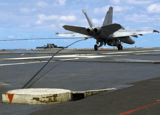
Aircraft carriers have angled flight decks so that takeoff and landing operations can occur simultaneously. In a way, carrier landings are controlled crashes, where pilots try to get their tail hooks to catch arresting wires for a successful landing. This doesn’t always happen on the first attempt, so pilots land at full power to ensure they have enough speed to take off if they miss (a “bolter”). Most navy pilots have boltered at some point in their career.
So why would you put a giant lift fan at the end of the landing strip and guarantee every bolter ended in a pilot’s demise? The visual effects team could have placed them anywhere.
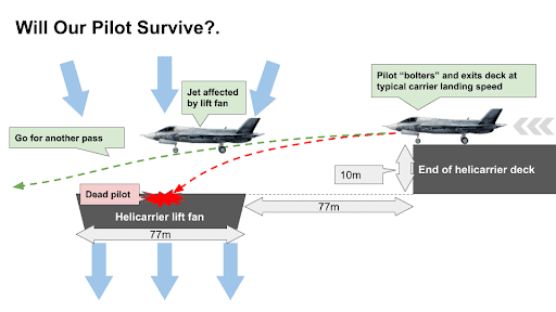
Given the Helicarrier design, what would it take for a pilot to survive a bolter landing attempt on the Helicarrier?
Modern simulation tools make answering these questions possible, and with access to Rescale, anyone can perform simulations that answer complex questions for engineering, design, or just for fun. So why not have some fun putting this sci-fi pseudo-engineering design to the test?
Setting Up the Problem: The Physics of a Helicarrier Landing
We start with the basic dimensions that matter for the above situation, based on the dimensions of modern aircraft carriers and what we see in the movie. For example, the lift fan is roughly the same width as the carrier’s main body. The lift fan is also the same distance away from the landing deck as the lift fan diameter.
Our pilot’s fate will likely depend on a few factors:
- The speed and pitch of the jet
- The mass of the jet
- Duration of the exposure to the lift fan’s airflow (based on the lift fan’s size)
- The forces on the jet due to the lift fan (based on the flow into the lift fan)
Also, we will make a few reasonable assumptions:
- The jet is flying at a typical aircraft carrier landing speed around 67 meters a second (m/s) or 150 mph
- As soon as the jet bolters, it’s basically flying at its landing speed just above the deck without touching it. We won’t worry about rolling resistance.
- We’ll assume the lightest configuration of the F-35 fighter jet for our analysis at 13,290 kg. No heavy payload on board etc.
- We’ll assume that the F-35 stays in the air pocket above the lift fan for only 1 second. (since it’s flying at 67 m/s and the fan is 77 meters wide)
- For all assumptions related to the lift fan velocity, we’ll refer you to a wicked cool blog by Rhett Allen in Wired magazine. He calculates the lift fan thrust airspeed of 642 m/s. To simplify the simulation, we will assume a much more conservative airspeed of 134 m/s.
- We’ll assume that the Helicarrier has inlet air vanes, properly placed, of course, so as not to create a giant vortex right above the lift fan right next to the runway!
- If the fighter jet drops any more than 10 meters, the fighter jet gets sucked into the lift fan, killing our pilot.
Aerodynamic Forces Can Be Simulated with Computational Fluid Dynamics Software
We’ll simulate the F-35 flying over a lift fan to calculate the lift and drag forces. But before we get into the simulation, let’s do a basic recap on how aircraft wings or airfoils work. This will help us better understand the simulation results and recognize any inaccurate answers that a simulation can sometimes generate.
For an airfoil to experience positive lift, the angle of attack is important. As the angle of attack increases, the lift coefficient increases up to a point, but beyond that, the airflow separates from the wing, and a stall occurs. This is known as the critical angle of attack.
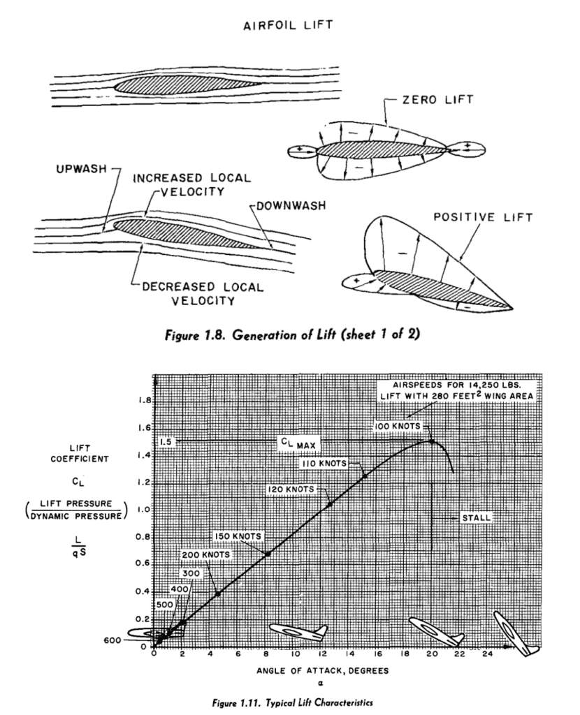
As shown in the figure above, at angles of attack higher than 20, the aircraft begins to stall.
Will a fighter jet be able to fly over a massive lift fan? As you might have guessed, the answer has to do with the angle of attack (AoA) and the velocity of the air over the airfoil. We’ll use a professional computational fluid dynamics (CFD) solver— Hexagon Cradle, to calculate both the AoA and velocity of air over the F-35.
Our simulation will be as simple as possible but sufficiently detailed to make an accurate calculation of lift and drag given certain assumptions:
- We will be simulating steady-state behavior
- We will assume that the flow is not rotating
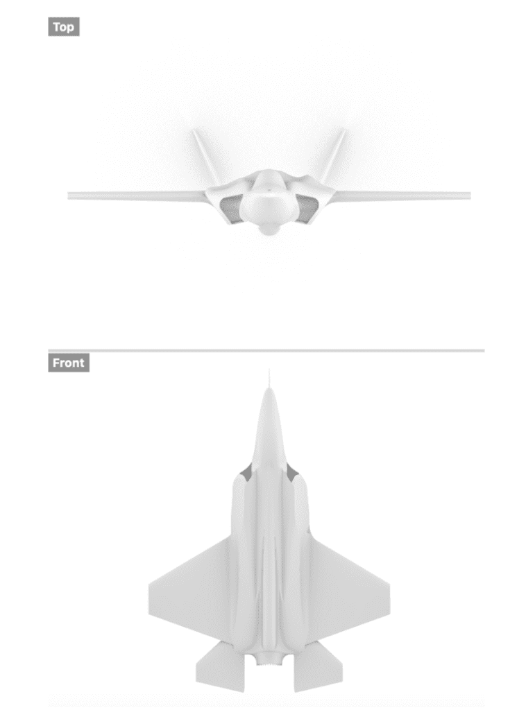
To simulate an F-35 fighter jet, we had to obtain a CAD model and properly smoothen the surfaces. Failing this irritates the meshing algorithm, and that’s never a good idea. We prepared a smoothened geometry representation of an F-35 in Rhino, as shown below.
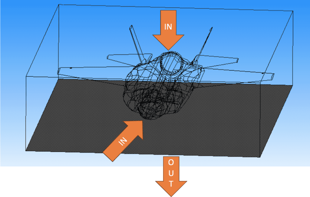
As the F-35 enters the air pocket above the lift fan:
- It has an initial velocity of 67 m/s. So, we will create an inlet flow condition of 67 m/s along the fuselage length.
- We’ll assume a much more conservative estimate of the fan thrust velocity of 134 m/s (compared to 642 m/s) perpendicular to the fuselage. We’ll create an inlet flow condition to represent this boundary condition.
- We’ll assume a static pressure of 0 Pa (Pascals) at the outlet at the plane right below the F-35.
- We’ll also assume free slip everywhere else.
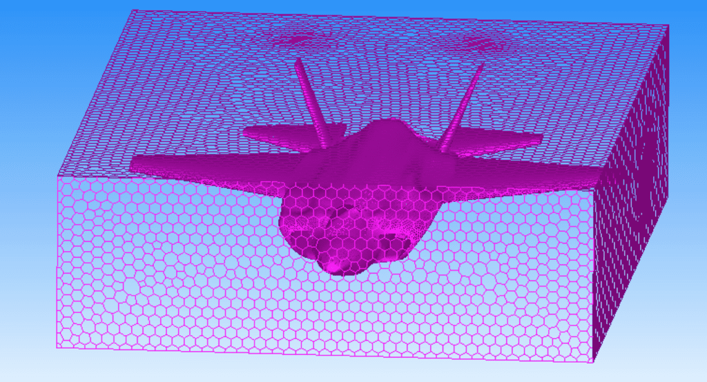
Finally, we prepared a very nice mesh for a good and accurate simulation.
And we were ready to simulate!
Once we got our CFD result, we plotted the pressure distribution on the aircraft body (shown below). Areas colored in red have higher pressure. We overlaid the pressure plot with velocity vector streamlines, shown as arrows below.
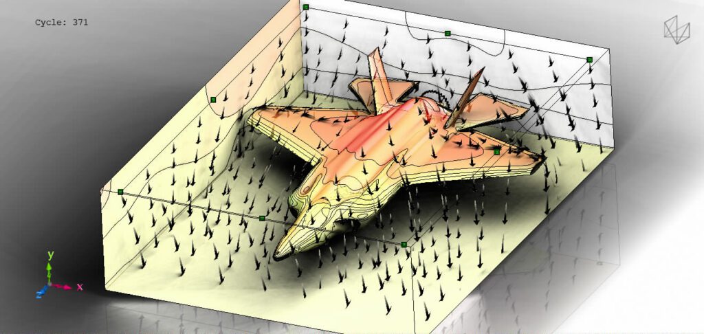
Finally, we calculated the overall downward force acting on the F-35. Assuming that the lift fan is sucking in air at 134 m/s, the overall downward force on the F-35 would be a whopping 1.773263 x 10^7 N.
Back to the hand calculations!
Stating what is known now:
- Initial horizontal velocity = 67 m/s
- Initial vertical velocity = 0 m/s (since it is initially moving horizontally)
- Force exerted = 1.773263 x 10^7 N
- Mass of F-35 = 13,290 kg
- Time for which the force is exerted = 1 s
- Gravitational acceleration (g) = 9.81 m/s²
First, let’s find the acceleration due to the aerodynamic force. Acceleration, a = F/m
a = 1.773263 x 10^7 N / 13,290 kg ≈ 1,334 m/s²
Now, let’s find the final vertical velocity (Vy) using the kinematic equation: V= U + a .t
Since the force is downward, the acceleration is negative (going opposite to the upward positive direction).
Vy= 0 m/s + (-1,334 m/s²)(1 s) = -1,334 m/s
Now, let’s find the distance moved downward (Sy) using the kinematic equation: S= u.t + 1/2 a .t2
Sy = 0 m/s(1 s) + (1/2)(-1,334 m/s²)(1 s)² = -667 m (downward)
For the horizontal motion, since no horizontal force is acting on the aircraft, it will continue to move at a constant velocity of 67 m/s.
The horizontal distance (Sx) is simply the horizontal velocity multiplied by the time.
Sx = 67 m/s * 1 s = 67 m
Our conclusion: The F-35 will move approximately 667 meters downward and 67 meters sideways. The Pilot will not survive impact to the lift fan, given the 667 meter drop.
With the help of simulations, we showed that the fighter jet would lose lift in the air pocket above the Helicarrier lift fan. That said, the pilot should speed up as much as possible and get as close to a 45-degree launch angle as possible.
Some additional caveats:
1. AoA was left at 0 deg, some pilots may pull up and enter the pocket above the lift fan at a different angle. This would improve lift and would be better for projectile motion. Our simulations ignore these scenarios.
2. They might also have deployed their flaps and landing gear, all of which will increase drag. Our simulations ignore these scenarios as well.
Democratizing Access to Simulation to Assist Early-Stage Design
Democratizing access to simulation is about making advanced simulation tools accessible and usable for a broader range of individuals, including those without specialized training in computational methods.
By simplifying the user interface and integrating simulations into the early stages of the design process, designers can quickly and effectively evaluate the performance and feasibility of various design concepts. This early-stage integration helps identify and weed out suboptimal design candidates, thus saving time and resources.
Cloud-based simulation platforms, as well as improved computational capabilities and algorithms, play a vital role in this democratization process. With easier access to these powerful tools, designers can innovate more efficiently and make data-driven decisions that lead to higher quality and more sustainable designs.
If designers and other non-CFD/HPC experts had easy access to simulation, could we avoid bad design candidates altogether? Only time will tell. The good news is that you won’t be waiting too long. Simulation technology is experiencing the most rapid innovation it has ever seen!

One last thing. Thanks to Rescale, the simulation in this blog was set up from a cabin on a lake!
With Rescale, Sandeep was able to quickly and easily access the tools he needed to explore this design issue, from cutting-edge simulation software to the right hardware for photorealistic image processing.
We are happy to report that today real engineering can happen anytime, anywhere.