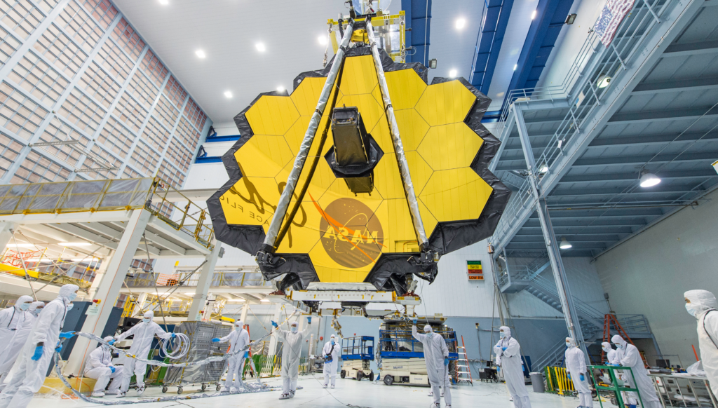

Harnessing the Potential of Finite Element Analysis: Transforming Engineering Design and Testing
With its ability to simulate real-world scenarios and provide valuable insights, finite element analysis (FEA) is an indispensable tool for engineers seeking to optimize designs, improve performance, and ensure the integrity of structures and components.
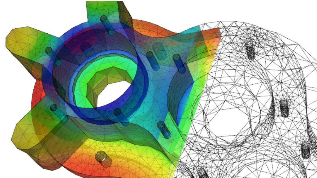
Finite Element Analysis (FEA) is a computational technique used to approximate and analyze the behavior of complex physical systems. It is based on the concept of dividing a continuous domain into smaller, finite subdomains called finite elements. Each element represents a portion of the domain, and together they form a mesh. Meshes are one of the most essential components in 3D modeling. A mesh for FEA is any object that an engineer can manipulate to form different shapes and forms that approximates the geometry of the system being analyzed.
In finite element analysis, the behavior of the system is described by a set of mathematical equations that govern its physical properties and interactions. These equations are typically derived from the principles of physics, such as Newton’s laws of motion or the equations of elasticity. By breaking up the system into finite elements, the complex equations can be approximated and solved numerically.
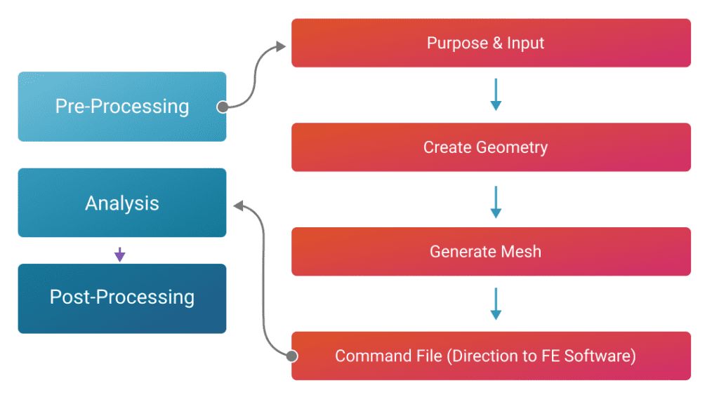
The FEA Process: Three Stages to Comprehensive Analysis
FEA typically involves three main stages, which are commonly referred to as preprocessing, solution, and post-processing. These stages are essential in conducting a comprehensive analysis of a physical system using the finite element method. Let’s delve into each stage:
- Preprocessing The preprocessing stage involves several tasks that lay the foundation for the analysis:
- Geometry and Mesh Generation: The geometry of the system is defined, either by importing a CAD model or creating it within the analysis software. The domain is then discretized into a mesh consisting of smaller finite elements, which approximate the system’s geometry.
- Material Properties: The material properties of the components within the system, such as elasticity, thermal conductivity, or fluid behavior, are specified.
- Boundary Conditions: The boundary conditions are defined, including constraints, loads, and constraints applied to the system. These conditions define how the system interacts with its environment or external forces.
- Element Types: The appropriate element types are selected based on the nature of the problem and the behavior of the system. Different element types, such as beams, shells, or solid elements, may be used to accurately represent the system’s geometry and physical behavior.
- Solution The solution stage involves solving the formulated equations to obtain the unknowns and generate results:
- Equation Assembly: The equations that describe the behavior of the system, such as the equations of motion or governing equations of heat transfer, are assembled based on the finite element “discretization.” This step involves combining the equations associated with individual elements to form a global system of equations.
- Numerical Solution: Various numerical methods, such as direct solvers or iterative techniques, are employed to solve the system of equations. The solution yields the values of the unknowns within the system, such as displacements, temperatures, or fluid velocities.
- Post-Processing The post-processing stage involves analyzing and interpreting the results obtained from the solution stage:
- Visualization: The results are visualized to aid in understanding the behavior of the system. This can include contour plots, deformation animations, or stress distribution maps.
- Quantitative Analysis: Quantities of interest, such as maximum stresses, displacements, or heat fluxes, are extracted and evaluated. These values are often compared against design criteria or standards to assess the performance of the system.
- Sensitivity Analysis and Optimization: Post-processing can involve sensitivity analysis or optimization techniques to explore the effects of design parameters or to optimize the system’s performance based on specific objectives.
By following these three stages, engineers and analysts can effectively apply the finite element method to study and gain insights into the behavior of complex physical systems and make informed engineering decisions.
Who Invented the Finite Element Method?
The finite element method (FEM) was developed by a number of researchers independently during the late 1950s and early 1960s. However, the credit for the formulation and popularization of the method is generally attributed to two individuals.
Richard Courant, a German mathematician, and his collaborators developed the earliest version of the finite element method in the 1940s and 1950s. They applied it primarily to problems in structural mechanics.
J. Tinsley Oden, an American mathematician, and engineer, made significant contributions to the development and application of the finite element method in the 1960s. He expanded its scope beyond structural mechanics to include various fields of engineering and physics.
It’s worth noting that the development of the finite element method involved contributions from many other researchers, and it has since been further refined and expanded by numerous scientists and engineers around the world.
What Is the Difference Between FEM and FEA?
The terms “FEM” (finite element method) and “FEA” (finite element analysis) are often used interchangeably and refer to the same underlying concept. However, if we were to make a distinction, it could be understood as follows.
The Finite Element Method: FEM is a mathematical modeling technique used to approximate and solve complex physical problems by dividing the problem domain into smaller, finite elements. It involves formulating the governing equations of the system, dividing the domain into finite elements, and solving the resulting equations numerically. FEM provides the mathematical framework and methodology for solving the problem.
Finite Element Analysis: FEA refers to the application of the finite element method to analyze and simulate the behavior of physical systems. It encompasses the entire process of using the FEM, including preprocessing (defining the geometry, creating the mesh, specifying material properties and boundary conditions), formulation (establishing the governing equations), solving the equations numerically, and post-processing (interpreting and analyzing the results). FEA is the practical implementation of the FEM for solving specific engineering problems.
In short, the FEM is the mathematical modeling method, while FEA is the practical application of that method to analyze and solve real-world problems. However, in common usage, the terms FEM and FEA are often used interchangeably to refer to the overall process of using the finite element method for analysis.
FEM and FEA Advantages
The finite element method has gained widespread popularity and is widely used in various fields of engineering and physics due to its versatility and ability to handle complex problems. It offers several advantages.
Flexibility: FEM can handle problems with complex geometries, material properties, and boundary conditions. It allows for the modeling of various physical phenomena, such as structural mechanics, heat transfer, fluid dynamics, electromagnetics, and more.
Adaptive Refinement: FEM allows for adaptive mesh refinement, where the mesh can be refined or coarsened in specific regions based on the requirements of the analysis. This enables efficient and accurate solutions, particularly in regions of interest or areas with significant gradients.
Accuracy: With appropriate mesh refinement and proper selection of element types, FEM can provide accurate results for a wide range of problems. It allows for capturing localized effects and can handle nonlinearities, such as material nonlinearity or large deformations.
Verification and Validation: FEM has been extensively studied, verified, and validated over many years, making it a trusted and widely accepted method for engineering analysis. Numerous commercial software packages are available with robust capabilities for FEA.
It’s important to note that the success of FEM/FEA relies on proper formulation, appropriate assumptions, accurate modeling of the system, and validation of results. Additionally, for specific problems, alternative analysis methods may be more suitable and offer advantages over FEM, such as analytical solutions, finite difference methods, boundary element methods, or computational fluid dynamics (CFD) techniques.
Ultimately, the choice between FEM/FEA and other analysis methods depends on factors such as the complexity of the problem, available resources, computational requirements, accuracy requirements, and the expertise of the analyst. It is often beneficial to consult with experts or experienced practitioners to determine the most appropriate analysis method for a specific problem.
Some Considerations When Using Finite Element Analysis
While finite element analysis (FEA) is a powerful and widely used technique, it does have certain limitations and disadvantages. Here are some of the common drawbacks associated with FEA.
Simplifying Assumptions: FEA requires making simplifying assumptions about the system being analyzed. These assumptions may not fully capture all the complexities and intricacies of the real-world behavior. Oversimplifications can lead to inaccurate results and misleading conclusions if the assumptions do not adequately represent the system.
Meshing and Element Selection: Generating an appropriate mesh is crucial for accurate results in FEA. However, meshing can be a challenging task, especially for complex geometries. The quality of the mesh, including element size, shape functions, and aspect ratio, can affect the accuracy and convergence of the analysis. Selecting the right element type for a specific problem is also important and requires expertise.
Computational Resources and Time: FEA often requires significant computational resources, including memory and processing power. Complex models with fine meshes can result in long computation times. Large-scale simulations may require high performance computing infrastructure, limiting the accessibility for smaller organizations or individuals.
Verification and Validation: Validating and verifying FEA results can be challenging, particularly for complex problems without analytical solutions or experimental data for comparison. Verification involves ensuring the accuracy of the numerical implementation, while validation involves comparing the FEA results against experimental or empirical data. Proper validation requires careful planning and testing.
Sensitivity to Inputs: FEA results can be sensitive to variations in input parameters, such as material properties, boundary conditions, or element sizes. Small changes in these parameters can lead to significant differences in the results. It is essential to carefully determine and characterize these inputs to obtain reliable and meaningful results.
User Expertise: Effective and accurate FEA requires a good understanding of the method’s underlying principles, modeling techniques, and software tools. Proper interpretation of results also requires expertise. Inadequate knowledge or improper application of FEA can lead to errors or misinterpretation of results.
Limitations of Physics Models: FEA relies on physics models and assumptions to describe the behavior of the system. These models may have limitations and may not accurately capture certain phenomena or behaviors. For example, FEA may struggle with problems involving complex fluid flow, highly nonlinear material behavior, or dynamic contact.
Despite these disadvantages, FEA remains a valuable and widely used tool for engineering analysis. With proper understanding, careful modeling, and validation efforts, many of these limitations can be mitigated, and accurate results can be obtained for a wide range of applications.
Who Uses FEA Analysis?
Finite element analysis (FEA) is utilized by various professionals and industries for engineering analysis and design. Some of the key users of FEA include:
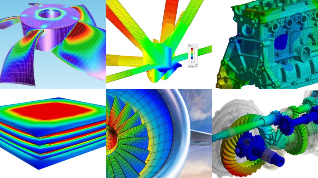
Mechanical Engineers: FEA is extensively employed by mechanical engineers for structural analysis, such as assessing the strength, stiffness, and deformation of mechanical components or systems. It aids in designing and optimizing structures like bridges, buildings, automotive components, aircraft parts, and machinery.
Civil Engineers: Civil engineers utilize FEA to analyze and design structures, including buildings, bridges, dams, tunnels, and other infrastructure projects. FEA helps evaluate structural integrity, stability, and load-bearing capacity, ensuring safety and efficiency in construction.
Aerospace Engineers: FEA plays a crucial role in the aerospace industry, where engineers employ it to analyze aircraft components, such as wings, fuselage, and landing gear, to ensure structural integrity, evaluate fatigue life, and optimize weight and performance.
Automotive Engineers: FEA is utilized extensively in the automotive industry to analyze and optimize vehicle components and systems, including chassis, suspension, engine parts, and safety systems. It aids in evaluating crashworthiness, noise and vibration, and overall performance.
Energy Industry: FEA is applied in the energy sector for analyzing various systems, including power plants, wind turbines, and pipelines. It helps in evaluating structural integrity, thermal analysis, fluid dynamics, and optimizing energy efficiency.
Electronics and Electrical Engineers: FEA is used in electronics and electrical engineering to analyze thermal management, electromagnetic behavior, and structural integrity of electronic components, circuit boards, and power distribution systems.
Biomedical Engineers: FEA finds applications in biomedical engineering, where it aids in analyzing and designing medical devices, prosthetics, implants, and modeling biological systems. It helps evaluate stress distribution, fluid flow, and biomechanical behavior.
Manufacturing Industry: FEA is employed in the manufacturing sector to optimize manufacturing processes, assess structural integrity of equipment, and simulate material behavior during forming, machining, or casting processes.
These are just a few examples, and FEA has widespread applications in many other industries and research fields. Its versatility allows engineers and scientists to simulate and predict the behavior of complex systems, aiding in design optimization, performance evaluation, and troubleshooting.
Continued Advancements and Use of FEA
Finite element analysis has revolutionized engineering analysis by providing a versatile and powerful approach to understanding the behavior of complex systems.
With its ability to simulate real-world scenarios and provide valuable insights, FEA is an indispensable tool for engineers seeking to optimize designs, improve performance, and ensure the integrity of structures and components. As FEA continues to advance, it will undoubtedly play a crucial role in shaping the future of engineering.
To learn more about how Rescale can power your digital explorations with finite element analysis (FEA), please contact our team of experts.